Every Geek should have one!
ESP32-S3 and the Estardyn 2.79-inch TFT LCD screen NV3007 small screen 142x428 display module 8-pin LCD color screen SPI
July 20th, 2026.
I've been trying for a while to get an ESP32-S3 SuperMini to talk to the Estardyn 2.79-inch TFT LCD screen. This screen is 142 x 428 and uses the NV3007 lcd controller driver. I tried various things and went down many internet rabbit-holes. Eventually I got something working.
The working code makes use of the Arduino_GFX library from moononournation. Tested with version V1.6.6. The source can be found here: https://github.com/moononournation/Arduino_GFX. It also makes use of U8G2 fonts so you will need the code from https://github.com/olikraus/u8g2. Testec with V2.3. Both can be installed from the Arduino IDE library manager.
The code below is a very simple Hello World program.
        #include <U8g2lib.h>

        #include <Arduino_GFX_Library.h>

        // Define all the ESP32-S3 pins being used

        #define LCD_DC 1
        #define LCD_CS 2
        #define LCD_RST 6
        #define LCD_SCK 12
        #define LCD_MOSI 11
        #define LCD_MISO -1
        #define LCD_BL 7

        // Define the display width and height.

        #define TFT_WIDTH 142
        #define TFT_HEIGHT 428

        // Build the hardware SPI bus. These values also work with the software SPI bus.

        Arduino_DataBus *bus = new Arduino_HWSPI(LCD_DC /* DC */, LCD_CS /* CS */, LCD_SCK /* SCK */, LCD_MOSI /* MOSI */, GFX_NOT_DEFINED /* MISO */);

        // Build the display driver

        Arduino_GFX *gfx = new Arduino_NV3007(
            bus,
            LCD_RST,
            1 /* rotation */,
            false /* IPS */,
            TFT_WIDTH /* width */,
            TFT_HEIGHT /* height */,
            12 /* col offset 1 */,
            0 /* row offset 1 */,
            14 /* col offset 2 */,
            0 /* row offset 2 */,
            nv3007_279_init_operations,
            sizeof(nv3007_279_init_operations));

        void setup(void)
        {
            Serial.begin(115200);
            delay(500);

            // Initialise the display

            if (!gfx->begin())
            {
                Serial.println("gfx->begin() failed!");
            }

            // Paint the screen black

            gfx->fillScreen(RGB565_BLACK);

            // Turn on the back light. Without this you will see nothing.

            pinMode(LCD_BL, OUTPUT);
            digitalWrite(LCD_BL, HIGH);

            // Set the font, colour, and size

            gfx->setFont(u8g2_font_maniac_tr);
            gfx->setTextColor(RGB565_WHITE);
            gfx->setTextSize(2);

            // Position the cursor and write out some text

            gfx->setCursor(50, 80);
            gfx->println("Hello, World!");
        }

        void loop()
        {
            delay(20);
        }
The code below extends this to add a smooth scrolling example. Smooth scrolling is achieved by making use us a canvas object. The text we want to scroll is written onto the canvas and then the canvas is drawn into the screen. After each write the X position is reduced by one and after a short delay the process repeated.
#include
#include

// Define all the ESP32-S3 pins being used

#define LCD_DC 1
#define LCD_CS 2
#define LCD_RST 6
#define LCD_SCK 12
#define LCD_MOSI 11
#define LCD_MISO -1
#define LCD_BL 7

// Define the display width and height.

#define TFT_WIDTH 142
#define TFT_HEIGHT 428

#define TFT_WIDTH_ROTATED 428
#define TFT_HEIGHT_ROTATED 142

// Build the hardware SPI bus. These values also work with the software SPI bus.

Arduino_DataBus *bus = new Arduino_HWSPI(LCD_DC /* DC */, LCD_CS /* CS */, LCD_SCK /* SCK */, LCD_MOSI /* MOSI */, GFX_NOT_DEFINED /* MISO */);

// Build the display driver

Arduino_GFX *gfx = new Arduino_NV3007(
      bus,
      LCD_RST,
      1 /* rotation */,
      false /* IPS */,
      TFT_WIDTH /* width */,
      TFT_HEIGHT /* height */,
      12 /* col offset 1 */,
      0 /* row offset 1 */,
      14 /* col offset 2 */,
      0 /* row offset 2 */,
      nv3007_279_init_operations,
      sizeof(nv3007_279_init_operations));

Arduino_Canvas *canvas;

uint16_t longTextHeight, longTextWidth;
int16_t scrollX = TFT_WIDTH_ROTATED - 100;
uint16_t scrollLineY = 15;
char *longTextToScroll = "The quick brown fox jumped over the lazy dog.";

void setup(void)
{
  Serial.begin(115200);
  delay(500);

  // Initialise the display

  if (!gfx->begin())
  {
    Serial.println("gfx->begin() failed!");
  }

  // Paint the screen black

  gfx->fillScreen(RGB565_BLACK);

  // Turn on the back light. Without this you will see nothing.

  pinMode(LCD_BL, OUTPUT);
  digitalWrite(LCD_BL, HIGH);

  // Set the font, colour, and size

  gfx->setFont(u8g_font_unifont);
  gfx->setTextColor(RGB565_WHITE);
  gfx->setTextSize(2);
  gfx->setTextWrap(false);

  // Position the cursor and write out some text

  gfx->setCursor(50, 110);
  gfx->println("Hello, World!");

  // Now setup the smooth scroll

  // How big is the text we want to scroll?

  int16_t x1, y1;
  gfx->getTextBounds(longTextToScroll, 0,0, &x1, &y1, &longTextWidth, &longTextHeight);

  // Build the canvas object

  canvas = new Arduino_Canvas(longTextWidth, longTextHeight, 0, 0, 0, 0);
  canvas->begin(GFX_SKIP_OUTPUT_BEGIN);

  // Set the font and write the long text into the canvas

  canvas->setFont(u8g_font_unifont);
  canvas->setTextColor(RGB565_YELLOW,RGB565_BLACK);
  canvas->setTextSize(2);
  canvas->setCursor(0,longTextHeight - 6);  // -6 takes us to the baseline
  canvas->fillScreen(RGB565_BLACK);
  canvas->print(longTextToScroll);
}

void loop()
{
  // Draw the bitmap at the given X, and Y.

  gfx->draw16bitRGBBitmap(scrollX,scrollLineY,canvas->getFramebuffer(),longTextWidth,longTextHeight);

  // Reduce the scroll position to move the text to the left

  scrollX -= 1;

  // Have we got to the end of the text

  if (scrollX + longTextWidth == TFT_WIDTH_ROTATED)
  {
    // Yes, dela for a short while and then clear the rectangle being drawn
    // into and reset the scroll position.

    delay(2000);
    scrollX = TFT_WIDTH_ROTATED - 100;
    gfx->fillRect(0, scrollLineY, TFT_WIDTH_ROTATED, longTextHeight, RGB565_BLACK);
  }

  delay(20);
}
The ESP32 and my iPhone
June 24th, 2026.
Many people make use of the ESP32 or similar embedded devices for IoT projects and, as you’d expect, all these projects connect to an Access Point through which they access the internet. This is fine when you’re home or at work, but what happens if you want to provide access to the internet via your iPhone. My initial attempts at this failed but it turns out to be quite easy.
The iPhone supports a personal hotspot. By default, this is called something like:
Martin’s iPhone
The apostrophe being used here is a curly Unicode apostrophe. It is not a plain ASCII apostrophe. Sadly, the ESP32 along with many embedded devices seem to reject SSID names containing non-ASCII characters.
The simple solution here is to remove the apostrophe altogether. This can be done by navigating to:
Settings | General | About | Name
There you can simply either remove the single quote or give the device a whole new name.
By default, the iPhone personal hotspot uses the 5GHz Wi-Fi band. Most embedded devices, including the ESP32, make use of the 2.4GHz band. To overcome this the iPhone “Maximise Compatibility” option needs to be enabled. Next navigate to:
Settings | Personal Hotspot
Where you will need to “Allow Others to Join”, provide a “Wi-Fi Password” if not already setup, and “Maximise Compatability”.
Once these changes have been made connectivity should be easy.
The Yaesu FT-707 Tuning Knob
February 7th, 2026.
I first got interested in Amateur Radio in my teens. I took the City and Guilds exam to get my B Class B license but always wanted to take the Morse test so I could buy my dream radio – the Yaesu FT-707. On my bedroom wall I had two posters. One was Fiona Walker cheekily pretending to play tennis. Sold by Athena posters if my memory serves me right. The other was the FT-707 sales brochure showing antenna tuner, power supply, radio, and memory unit in a metal rack.
When you look at the FT-707 your eye is drawn to the VFO running knob. It is easy to grip. The indentations around the edge are there to ensure a firm hold. The dimple is there to ease fine tuning. It is a master class in ergonomic design.
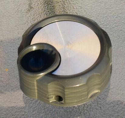
Many years later I was looking for a VFO tuning knob for a project. I tried several but none felt right. I decided to try reproducing the look and feel of the FT-707 VFO knob using my 3d printer.
My chosen design software is OpenSCAD. I’ve been programming my entire working life and the model it uses fits well with that. Building objects with OpenSCAD is simply a matter of creating the start object and then adding another object to it or remove an object from it. You then repeat the process until you have the object you need. For example, a washer would simply be a low-profile cylinder with a smaller cylinder removed from the centre.
It took a few iterations, but the result is quite pleasing.
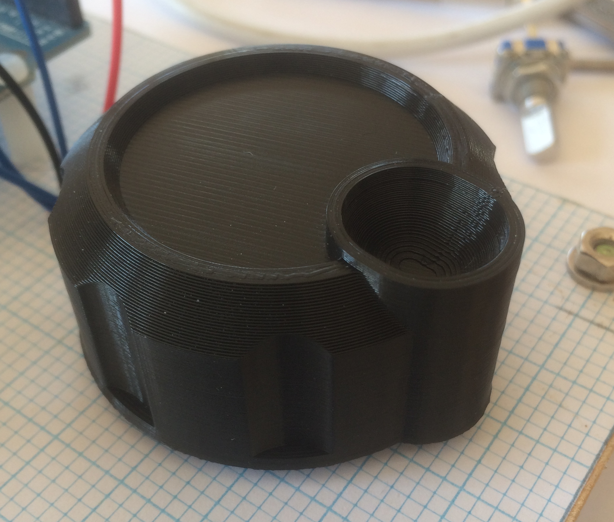
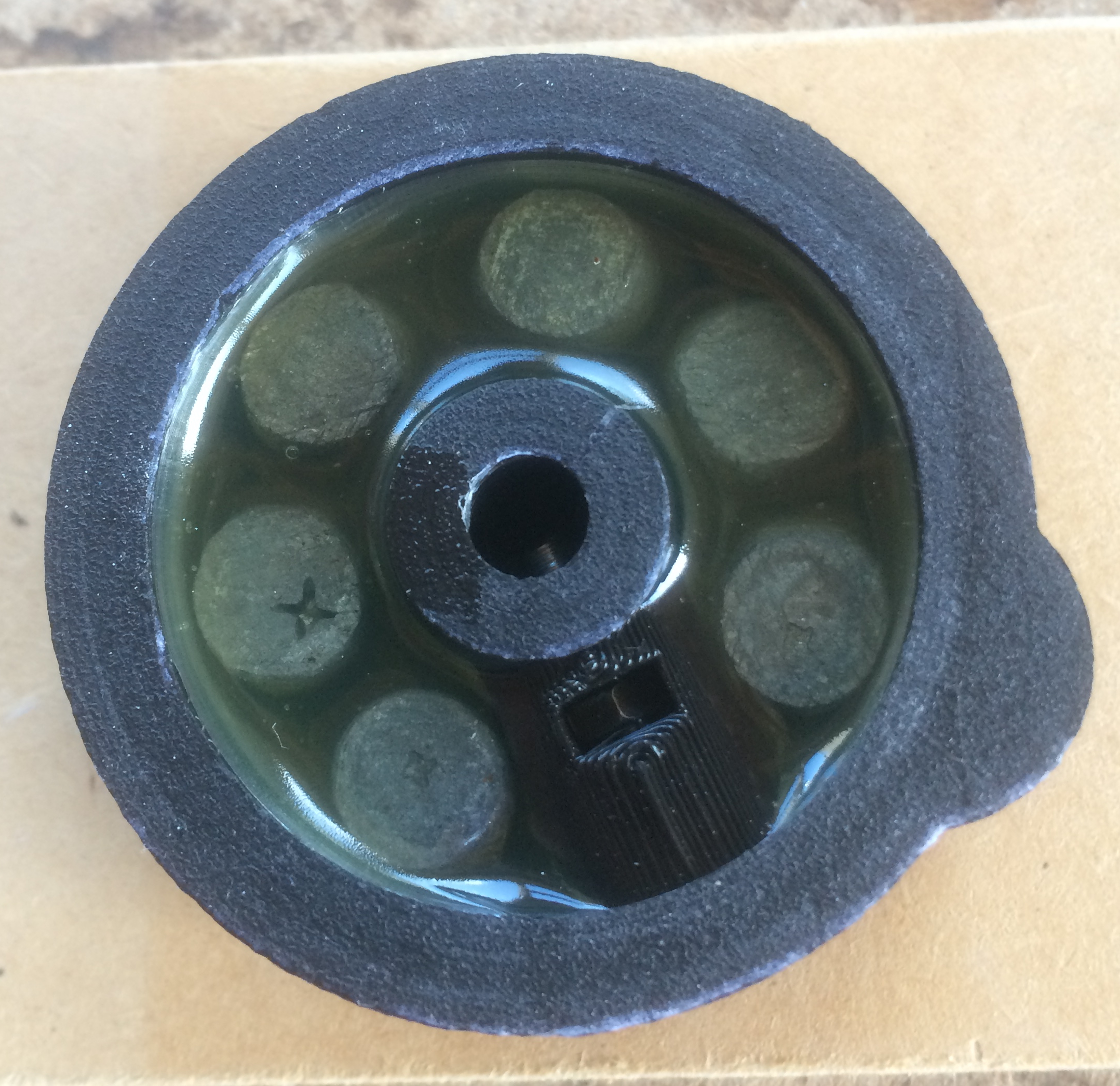
It has a small hole on the side, and a small nut and bolt can be used as grub screw to secure the knob to a rotary encoder shaft. It worked well; it did what it needed to do but there was something missing. It needed weight, it needed to have momentum. The back of the knob was hollow, and I resolved the momentum issue by adding lead weights. Being a bit of a hoarder – how small does an offcut of wooden need to be to be useless? – I had in stock some small pleasing lead cylinders that were recycled from an old piano. There was one in every key to act as the key return mechanism. Six of these fitted nicely in the recess. I encased the weights in epoxy resin. With the edition of the weights, it felt a great deal better, it felt like an FT-707.
The OpenSCAD project file can be found here. You may need to change the extension to scad.
The STL file can be found here.
Bridging the gap. NMEA 0183 to NMEA 2000.
January 13th, 2026.
NMEA 0183 first surfaced in the early 1980’s. It encompasses an electrical specification and data specification and is extensively used to share data between marine electronics. It became the standard and was seen on all vessel sizes from small yachts to the largest super tankers. Though popular it had issues. Primarily speed, it utilised serial data at 4800 baud. Also, if many sensors were feeding data to single devices or multiple devices then multiplexors and repeaters often had to be used.
NMEA 2000 was released in 2001 and aimed to provide a simplified, high speed, multidevice network based on the automotive CAN bus. Simplified as it manifests as a single network cable with devices attached via simple drop cables. Faster as data flows at 250 kilobits per second, considerably faster than the 4.8 kilobits per second supported by NMEA 0138.
The big difference between NMEA 0183 and NMEA 2000 is the format of the data. NMEA 0183 passes human readable text that can easily be visually inspected and interpreted. NMEA 2000 passed proprietary binary data packets, with some messages being spread across multiple packets.
From the amateur yachtsman point of view NMEA 2000 raised the bar considerably. With NMEA 0183 they may have been tempted to write their own code, or even build their own devices, to interpret or generate data, that flows around their boat. With NMEA 2000 more complicated hardware is required and, on top of that, a clear understanding of the proprietary protocol being used.
Fortunately, a few dedicated people have taken time to decode the NMEA 2000 protocol and, looking around the internet, you can now find code libraries and examples of how to interface to the NMEA 2000 network.
So, what is required? My go to hardware would be an ESP32 on which to run the code, and a SN65HVD230 CAN Bus Transceiver Communication module to interface to the network. These are cheap components; the biggest expense will probably be the network T junctions and drop cables. My go to software would be that written by Timo Lappalainen, his software can easily be found on GitHub. With this combination I have seen the most novice of developers reading data from their yacht network.
Why can this be useful? Most amateur sailors run their yachts on a tight budget and may be in a position of transitioning from the old NMEA 0183 devices to NMEA 2000 devices. Commercial kit is available to connect NMEA 0183 devices to an NMEA 2000 network, but they tend to be expensive. This may lead to some older NMEA 0183 devices being made redundant. Perhaps the adventurous sailor would be tempted to build their own.
One example that I have recently worked on involved an old Silicon Marine exhaust temperature sensor. It was an NMEA 0183 device that wrote out simple NMEA 0183 MTW water temperature sentences through a serial port. The project required that this data be read and published to an NMEA 2000 network to be displayed on a Raymarine data display. Using the hardware and software mentioned above the result proved to be very satisfying. Not only did the water temperature get correctly published but it was also able to raise temperature alarms should the exhaust water temperature exceed a configurable temperature.